

Eliwell Controller Manual: A Comprehensive Guide
This guide details Eliwell controllers, covering configuration, troubleshooting, and advanced features like alarms and communication protocols, ensuring optimal system performance.
Eliwell controllers are sophisticated electronic devices designed for precise temperature and process control across diverse applications. These controllers, renowned for their reliability and accuracy, are integral to industries like refrigeration, HVAC, and industrial automation. They offer a user-friendly interface coupled with advanced functionalities, enabling efficient management of complex systems.
Eliwell’s commitment to innovation is reflected in their diverse product range, catering to both simple and intricate control needs. Understanding the core principles of operation and configuration is crucial for maximizing their potential. This manual serves as a comprehensive resource, guiding users through every aspect of Eliwell controller usage, from initial setup to advanced troubleshooting, ensuring optimal performance and longevity of your equipment.
What are Eliwell Controllers Used For?
Eliwell controllers are versatile instruments employed in a wide spectrum of applications demanding precise temperature and process regulation. Primarily, they excel in refrigeration systems – managing compressors, evaporators, and condensers for optimal cooling performance. They are also extensively used in Heating, Ventilation, and Air Conditioning (HVAC) systems, ensuring comfortable and energy-efficient climate control.
Beyond these core areas, Eliwell controllers find application in industrial processes like food processing, plastics manufacturing, and pharmaceutical production. Their ability to maintain stable temperatures and control humidity is vital for product quality and safety. Furthermore, they are utilized in specialized applications such as cold room monitoring, supermarket refrigeration, and laboratory equipment control, demonstrating their adaptability and precision.
Eliwell Controller Series Overview (e.g., IC200, EWPC)
Eliwell offers a diverse range of controller series, each tailored to specific application needs. The IC200 series represents a compact and cost-effective solution for basic temperature control, ideal for smaller refrigeration units and HVAC systems. It features a user-friendly interface and essential control functions.
The EWPC series, conversely, provides advanced capabilities, including Modbus communication, data logging, and sophisticated alarm management. This series is suited for complex industrial processes and larger installations requiring remote monitoring and control. Other notable series include the ELCO, designed for electric heating, and specialized controllers for specific applications like evaporative condensers. Each series boasts unique features and functionalities, catering to a broad spectrum of control requirements.

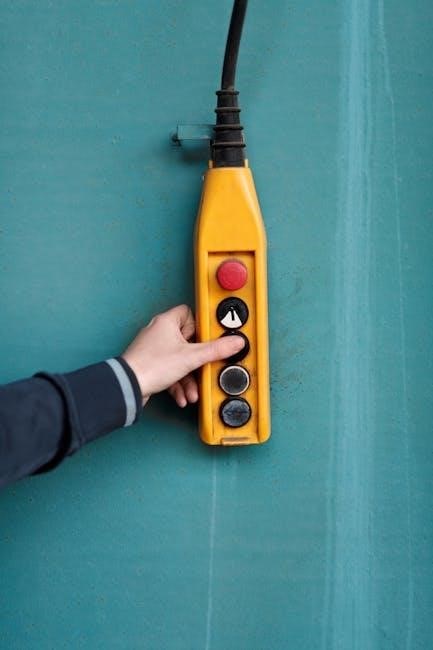
Understanding the Eliwell Controller Interface
The Eliwell interface features a clear display, intuitive keypad, and logical menu structure for easy navigation and efficient parameter adjustment.
Display and Navigation
The Eliwell controller display provides crucial real-time information, including the current process value, setpoint, and output status. Typically, a backlit LCD or LED screen ensures visibility in various lighting conditions. Navigation is primarily achieved through a keypad, allowing users to scroll through menus and adjust parameters.
Controllers often employ a hierarchical menu structure, organizing settings into logical categories for easier access. Common navigation keys include “Up,” “Down,” “Enter,” and “Escape.” The display may also feature indicators for alarm status, communication activity, and sensor input. Understanding the display’s icons and symbols is vital for effective operation. Some models offer multiple display pages, accessible via dedicated keys, to show additional data or configurations.
Keypad Functions and Operation
The Eliwell controller keypad is the primary interface for user interaction. Standard keys include arrow keys (Up, Down, Left, Right) for menu navigation and parameter selection. The “Enter” or “OK” key confirms selections, while “Escape” or “Back” returns to the previous menu. Numerical keys facilitate direct input of setpoints and other values.
Some models feature dedicated function keys for quick access to frequently used settings, like alarm acknowledgment or program selection. Keypad operation often involves a multi-level menu system; pressing a key may cycle through options or open submenus. A long press on a key can sometimes activate alternative functions. Refer to the specific model’s manual for a detailed explanation of each key’s functionality and any unique operational characteristics.
Understanding the Menu Structure
Eliwell controller menus are typically hierarchical, organized into logical sections for ease of navigation. Common top-level menus include “Settings,” “Parameters,” “Alarms,” “Communication,” and “Information.” Within each section, submenus provide access to specific settings and data. The “Settings” menu usually handles basic configurations like clock, date, and units.
“Parameters” allows adjustment of control variables like setpoints, PID gains, and hysteresis. “Alarms” manages alarm thresholds and acknowledgment settings. “Communication” configures serial or network connections. Understanding this structure is crucial for efficient operation. Navigation is usually achieved using the keypad’s arrow keys, with “Enter” selecting options and “Escape” returning to the previous level.

Basic Controller Configuration
Initial setup involves setting the correct time, date, and preferred temperature units (°C or °F) for accurate operation and data logging.
Setting the Clock and Date
Accurate time and date settings are fundamental for proper Eliwell controller operation, enabling correct data logging, alarm timestamps, and scheduled programming. Access the controller’s menu, typically through the navigation keys, and locate the ‘Date/Time’ or similar setting.
Use the keypad to adjust the year, month, day, hour, and minute. Ensure the correct format (MM/DD/YYYY or DD/MM/YYYY) is selected. Some models may offer automatic time synchronization via external sources. Verify the settings after adjustment; incorrect time can lead to errors in data analysis and control sequences. Regularly check and update the clock, especially after power outages, to maintain system reliability and accurate record-keeping.
Configuring Temperature Units (°C or °F)
Selecting the correct temperature unit – Celsius (°C) or Fahrenheit (°F) – is crucial for accurate temperature monitoring and control within the Eliwell system. Navigate to the ‘Settings’ or ‘Configuration’ menu using the controller’s keypad. Locate the ‘Temperature Units’ option, which may be under a ‘Display’ or ‘General’ submenu.
Use the arrow keys to toggle between °C and °F. Confirm your selection and exit the menu. Ensure all temperature displays and setpoints reflect the chosen unit. Incorrect unit selection can lead to misinterpretation of readings and improper control actions. Double-check this setting during initial setup and after any controller resets to guarantee consistent and reliable operation.
Language Settings
Eliwell controllers often support multiple languages to cater to a diverse user base. Access the ‘Settings’ or ‘Configuration’ menu via the controller’s interface. Within this menu, locate the ‘Language’ option; it’s frequently found under ‘Display’ or ‘System’ settings. Use the up/down arrow keys to scroll through the available language options, such as English, French, Spanish, or Italian.
Select your preferred language and confirm your choice. The controller’s display and menu prompts will then switch to the selected language. This feature enhances usability for operators who are more comfortable with a language other than the default. Remember to note the original language setting before changing it, for easy reversion if needed.
Sensor Configuration and Calibration
Proper sensor setup is crucial for accurate readings. This section covers supported sensor types, calibration steps, and troubleshooting potential sensor error issues.
Supported Sensor Types (PT100, Thermocouples, etc.)
Eliwell controllers demonstrate versatility by accommodating a wide array of temperature sensors, ensuring compatibility with diverse industrial applications. Commonly supported types include PT100 resistance temperature detectors (RTDs), known for their accuracy and stability, and various thermocouple types (J, K, T, E, N, R, S, and B) offering broad temperature ranges.
Additionally, some models support thermistors and analog voltage/current inputs for specialized sensing needs. The controller’s configuration menu allows precise selection of the sensor type, enabling accurate temperature measurement and control. Proper sensor selection is vital for optimal performance, considering factors like temperature range, accuracy requirements, and environmental conditions.
Sensor Calibration Procedures
Maintaining sensor accuracy is crucial for reliable control. Eliwell controllers offer calibration routines to compensate for sensor drift or inaccuracies. Typically, this involves a one- or two-point calibration process, comparing the controller’s reading to a known, accurate temperature standard.
Access the calibration menu through the controller interface, and follow the on-screen prompts to input the reference temperature values. The controller then adjusts its internal parameters to match the reference, improving measurement precision. Regular calibration, guided by the manufacturer’s recommendations, ensures consistent and dependable performance. Documenting calibration dates and results is best practice.
Addressing Sensor Errors
When a sensor error occurs, the Eliwell controller displays a specific error code, indicating the nature of the problem. Common issues include open circuits (sensor disconnected), short circuits, or out-of-range readings. First, visually inspect the sensor and wiring for any physical damage or loose connections.
If the wiring appears sound, attempt a sensor recalibration. If the error persists, the sensor itself may be faulty and require replacement. Consult the controller’s manual for a complete list of error codes and their corresponding solutions. Proper grounding and shielding can minimize electrical interference, preventing false readings and errors.
Programming Control Parameters
Effectively adjust setpoints, hysteresis, and PID parameters (P, I, D) for precise temperature control, alongside utilizing ramp and soak programming features.
Setting Setpoints and Hysteresis
Setting accurate setpoints is crucial for maintaining desired process temperatures. The setpoint defines the target temperature the Eliwell controller aims to achieve. Hysteresis, conversely, introduces a temperature range around the setpoint, preventing rapid cycling of the control output.
A wider hysteresis value reduces the frequency of on/off switching, extending the life of relays or other control devices. Conversely, a narrower hysteresis provides tighter temperature control but may lead to more frequent cycling.
Eliwell controllers allow independent setpoint configuration for heating and cooling, enabling precise control across a broad temperature spectrum. Proper adjustment of both parameters ensures stable and efficient operation, minimizing energy consumption and maximizing process quality.
Configuring PID Parameters (P, I, D)
PID (Proportional, Integral, Derivative) control is fundamental to Eliwell controller operation, enabling precise temperature regulation. The Proportional band reacts to the current error, the Integral eliminates steady-state errors, and the Derivative anticipates future errors based on the rate of change.
Adjusting these parameters – P, I, and D – fine-tunes the controller’s response. A higher P value increases responsiveness but can cause oscillation. Increasing I eliminates offset but can lead to instability. D dampens oscillations but can slow response time.
Optimal PID tuning requires understanding the process dynamics and iteratively adjusting parameters to achieve stable, accurate, and responsive control. Eliwell controllers often offer auto-tuning features to assist with this process.
Ramp and Soak Programming
Eliwell controllers excel in applications requiring complex thermal profiles through Ramp and Soak programming. Ramp functionality defines a controlled heating or cooling rate to a target temperature, specified in °C or °F per minute/hour. Soak programming maintains a constant temperature for a defined duration, crucial for processes like curing or stabilization.
These features allow creation of multi-stage profiles, automating intricate processes. Users can define multiple ramps and soaks sequentially, creating a precise thermal history.
Proper configuration ensures accurate process control and repeatable results. Careful consideration of ramp rates and soak times is essential for optimal performance and product quality.

Advanced Features and Functions
Explore Eliwell’s sophisticated capabilities, including customizable alarm systems, diverse communication protocols like Modbus, and comprehensive data logging for analysis.
Alarm Configuration and Management
Eliwell controllers offer robust alarm functionality crucial for process monitoring and safety. Users can configure multiple alarm thresholds for various parameters, including temperature, pressure, and humidity. These alarms can be configured as high or low limits, with adjustable hysteresis to prevent nuisance tripping.
Different alarm types are available, such as immediate alarms triggering instant responses, and delayed alarms providing a time buffer. Alarm outputs can activate relays for external signaling, audible alerts, or system shutdowns. Effective alarm management involves defining clear alarm priorities and assigning appropriate responses. Regularly reviewing alarm logs helps identify recurring issues and optimize system performance. Proper configuration ensures timely intervention during critical events, safeguarding equipment and processes.
Communication Protocols (Modbus, etc.)
Eliwell controllers support various communication protocols, enabling seamless integration into larger automation systems. Modbus is a commonly supported protocol, allowing controllers to exchange data with PLCs, HMIs, and SCADA systems. Other protocols like BACnet may also be available depending on the specific model.
Configuration involves setting communication parameters such as baud rate, parity, and address. Proper protocol setup ensures reliable data transmission and remote control capabilities. Utilizing these protocols facilitates centralized monitoring, data logging, and remote adjustments of controller settings. Secure communication practices are essential to prevent unauthorized access and maintain system integrity.
Data Logging and Export
Eliwell controllers often feature built-in data logging capabilities, recording critical parameters like temperature, humidity, and pressure over time. This historical data is invaluable for performance analysis, troubleshooting, and regulatory compliance. Logged data can typically be accessed through the controller’s interface or via communication protocols like Modbus.
Export options usually include formats like CSV or text files, facilitating data import into spreadsheets or specialized analysis software. Configuring logging intervals and storage capacity is crucial for efficient data management. Regularly exporting and archiving data ensures long-term preservation and prevents data loss.
Troubleshooting Common Issues
This section addresses frequent problems, including error codes, communication failures, and sensor malfunctions, providing solutions for quick and effective resolution.
Error Codes and Their Meanings
Eliwell controllers utilize a comprehensive error code system to diagnose operational issues. These codes, displayed on the unit’s interface, pinpoint the source of the problem, ranging from sensor failures to communication errors. For instance, a code indicating a “High Temperature” fault suggests a sensor reading exceeding the setpoint, or a potential sensor malfunction.
Conversely, a “Low Temperature” error signals readings below the threshold. Communication errors, often denoted by specific codes, indicate issues with Modbus or other connected protocols. Regularly consulting the specific model’s manual is crucial, as error code definitions vary between Eliwell controller series (IC200, EWPC, etc.). Understanding these codes empowers users to efficiently troubleshoot and resolve issues, minimizing downtime and ensuring optimal system performance.
Addressing Communication Problems
Communication issues with Eliwell controllers often stem from incorrect Modbus settings, wiring faults, or protocol mismatches. Begin by verifying the physical connections – ensuring secure wiring and proper termination resistors. Confirm the controller’s communication parameters (baud rate, parity, stop bits) align with the master device.
Check for address conflicts if multiple devices share the same network; Utilize diagnostic tools within the controller’s interface to test communication integrity. If using Modbus TCP/IP, verify network connectivity and firewall settings; Refer to the specific model’s manual for detailed troubleshooting steps and protocol-specific guidance. A systematic approach, combined with careful verification of settings, is key to resolving communication challenges.
Resolving Sensor Malfunctions

Sensor malfunctions in Eliwell controllers typically manifest as erratic readings, out-of-range values, or complete signal loss. Initially, inspect the sensor wiring for breaks, shorts, or loose connections. Verify the sensor type configured in the controller matches the physically installed sensor (PT100, thermocouple, etc.).
Perform sensor calibration procedures as outlined in the manual to correct any drift or inaccuracies. If the issue persists, try swapping the sensor with a known-good unit to isolate the problem. Check for environmental factors affecting sensor performance, such as excessive temperature or electromagnetic interference. Consult the error code documentation for specific diagnostic guidance;

Safety Precautions and Maintenance
Prioritize electrical safety during maintenance; regularly clean the controller and back up its configuration to prevent data loss and ensure longevity.
Electrical Safety Guidelines
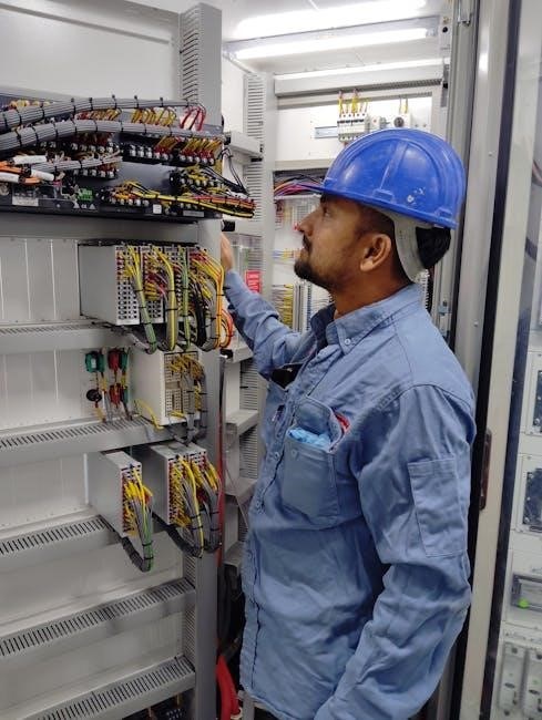
Working with Eliwell controllers involves electrical components, demanding strict adherence to safety protocols. Always disconnect power before accessing internal wiring or components to prevent electrical shock. Ensure proper grounding of the controller and associated equipment to minimize risk.
Qualified personnel should perform all electrical work, following local and national electrical codes. Never operate the controller with damaged power cords or connections. Regularly inspect wiring for wear and tear, replacing damaged parts immediately. Avoid contact with live circuits and utilize insulated tools.
Be aware of voltage levels and potential hazards. Proper labeling of electrical components is crucial for safe maintenance. Implement Lockout/Tagout procedures during servicing to prevent accidental energization.
Cleaning and Maintenance Procedures
Regular cleaning extends the lifespan of your Eliwell controller. Disconnect power before cleaning; use a soft, dry cloth to wipe the exterior, avoiding abrasive cleaners or solvents. Do not apply liquids directly to the unit. Periodically inspect the keypad and display for dust accumulation, gently removing it with compressed air.
Check terminal connections for tightness and corrosion, addressing any issues promptly. Inspect the internal components (with power off and by qualified personnel) for dust buildup, carefully removing it.
Avoid operating the controller in excessively humid or dusty environments. Document all maintenance activities for future reference and troubleshooting.
Controller Backup and Restore
Regularly backing up your Eliwell controller’s configuration is crucial for disaster recovery. Utilize the controller’s built-in backup function (if available) to save settings to a removable storage device, like a USB drive. Alternatively, employ dedicated software provided by Eliwell for PC-based backups.
Store backup files in a secure, off-site location. In case of controller failure or accidental parameter changes, restore the configuration by loading the backup file.
Verify the restored settings before resuming operation. Document the backup and restore procedures for easy reference.

Specific Model Manuals and Resources
Access detailed Eliwell IC200 and EWPC manuals online, alongside FAQs and support forums, for model-specific guidance and troubleshooting assistance.
Eliwell IC200 Manual Location
Finding the Eliwell IC200 manual is crucial for effective operation and troubleshooting. The official Eliwell website is the primary source, often requiring a search using the specific IC200 model number (e.g., IC200-160, IC200-240).
Alternatively, numerous online resources archive these manuals, including dedicated HVAC/R forums and document repositories. A targeted web search using terms like “Eliwell IC200 manual PDF” will yield relevant results.
Ensure the downloaded manual corresponds to your exact IC200 model to avoid incorrect information. The manual typically covers installation, configuration, programming, and error code explanations, vital for maintaining optimal performance.
Always prioritize official Eliwell documentation when available, as third-party sources may contain inaccuracies.
Eliwell EWPC Manual Location
Locating the Eliwell EWPC manual is essential for proper setup and maintenance of your control system. Begin your search on the official Eliwell website; navigate to the ‘Support’ or ‘Downloads’ section and filter by the EWPC series.
Specify your exact EWPC model number (e.g., EWPC 160, EWPC 240) for accurate results, as variations exist. If the official site proves unhelpful, explore specialized HVAC/R documentation websites and forums.
A focused online search using keywords like “Eliwell EWPC manual PDF” will often uncover downloadable resources.
Verify the manual’s authenticity and model compatibility before relying on its contents.
Accessing Online Support and FAQs
Eliwell provides comprehensive online support resources to assist users with their controllers. Start by visiting the official Eliwell website and navigating to the ‘Support’ or ‘Contact Us’ section. Here, you’ll find a frequently asked questions (FAQ) database addressing common issues and configurations.
Many HVAC/R forums and online communities dedicated to industrial controls feature discussions about Eliwell controllers, offering peer-to-peer support and troubleshooting advice.
Consider utilizing Eliwell’s online knowledge base, if available, for detailed articles and guides.
Directly contacting Eliwell’s technical support team via email or phone is an option for complex problems.